
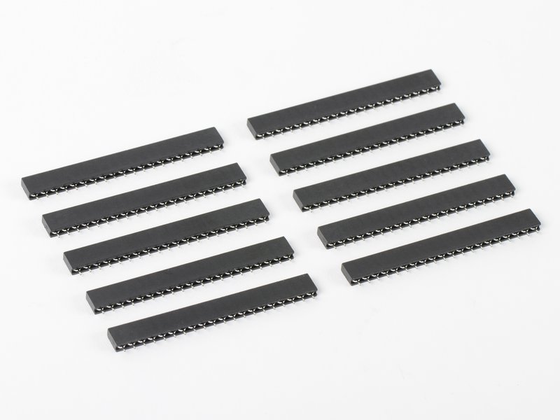


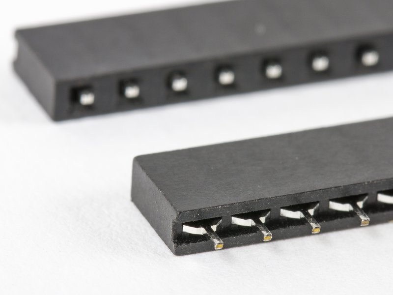
Flip-Pins are Integrated Circuit (IC) pins designed by Fliptronics for use in products like OSHChip. Flip-Pins are designed to create pins that can be soldered into a Printed Circuit Board (PCB) and look as much like an IC pin as possible. With the unique plastic aligner, the pins are held 0.100" apart, with a 0.062" solder tail exposed.
 A significant feature of Flip-Pins is that their width (0.020") is the same as traditional Dual-Inline-Package (DIP) IC pins, and so Flip-Pins are directly compatible with standard breadboards. Many people use header pins which are square to connect their PCBs to breadboards, and are unaware that header pins damage the breadboard because they are wider than standard DIP pins. PCBs that use Flip-Pins are easier to insert and remove from breadboards, compared to PCBs with header pins.
Flip-Pins are available in 3 lengths: 8, 14, and 20 pins. Other lengths can be achieved by either using multiple strips, or removing pins from a strip.
Flip-Pins are compatible with IC sockets that have flat contacts. Flip-Pins might not be compatible with IC sockets that have a round entry hole for the IC pin.
Many types of PCBs and breakout boards can be used with Flip-Pins.
How Flip-Pins are used
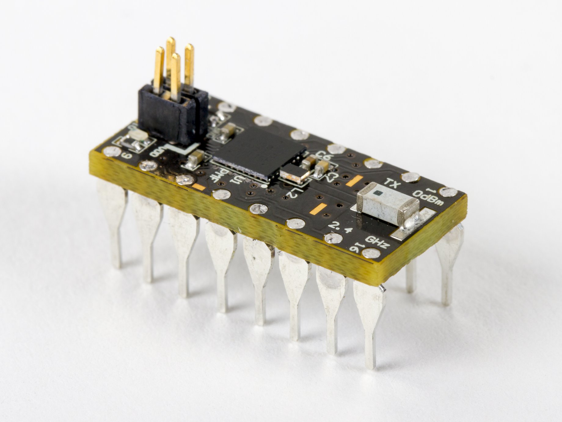
When soldered into PCBs that are commonly 0.062" thick, a near flush surface can be achieved on the non-pin side of the PCB (see the OSHChip on a penny picture, above). After soldering the pins into your PCB, the plastic aligner can be easily removed and discarded.
A significant feature of Flip-Pins is that their width (0.020") is the same as traditional Dual-Inline-Package (DIP) IC pins, and so Flip-Pins are directly compatible with standard breadboards. Many people use header pins which are square to connect their PCBs to breadboards, and are unaware that header pins damage the breadboard because they are wider than standard DIP pins. PCBs that use Flip-Pins are easier to insert and remove from breadboards, compared to PCBs with header pins.
Flip-Pins are available in 3 lengths: 8, 14, and 20 pins. Other lengths can be achieved by either using multiple strips, or removing pins from a strip.
Flip-Pins are compatible with IC sockets that have flat contacts. Flip-Pins might not be compatible with IC sockets that have a round entry hole for the IC pin.
Many types of PCBs and breakout boards can be used with Flip-Pins.
How Flip-Pins are used
When soldered into PCBs that are commonly 0.062" thick, a near flush surface can be achieved on the non-pin side of the PCB (see the OSHChip on a penny picture, above). After soldering the pins into your PCB, the plastic aligner can be easily removed and discarded.
 The recommended footprint on your PCB for Flip-Pins is shown in the datasheet. Briefly, the holes should be 0.025" in diameter, and the associated pads should be at least 0.040" in diameter. On the top side of your PCB (the side that does not have the pins) you can place components and vias close to the pads. On the bottom of the PCB, you must leave clearance for the plastic aligner. For the narrow dimension, the clearance should be 0.120" centered on the center line of the row of pins. For the length, the clearance area should be 0.100" times the number of pins +0.040". For example, for the 14 pin version of Flip- Pins, the clearance area is 0.120" x 1.440".
Documentation:
The recommended footprint on your PCB for Flip-Pins is shown in the datasheet. Briefly, the holes should be 0.025" in diameter, and the associated pads should be at least 0.040" in diameter. On the top side of your PCB (the side that does not have the pins) you can place components and vias close to the pads. On the bottom of the PCB, you must leave clearance for the plastic aligner. For the narrow dimension, the clearance should be 0.120" centered on the center line of the row of pins. For the length, the clearance area should be 0.100" times the number of pins +0.040". For example, for the 14 pin version of Flip- Pins, the clearance area is 0.120" x 1.440".
Documentation:
A significant feature of Flip-Pins is that their width (0.020") is the same as traditional Dual-Inline-Package (DIP) IC pins, and so Flip-Pins are directly compatible with standard breadboards. Many people use header pins which are square to connect their PCBs to breadboards, and are unaware that header pins damage the breadboard because they are wider than standard DIP pins. PCBs that use Flip-Pins are easier to insert and remove from breadboards, compared to PCBs with header pins.
Flip-Pins are available in 3 lengths: 8, 14, and 20 pins. Other lengths can be achieved by either using multiple strips, or removing pins from a strip.
Flip-Pins are compatible with IC sockets that have flat contacts. Flip-Pins might not be compatible with IC sockets that have a round entry hole for the IC pin.
Many types of PCBs and breakout boards can be used with Flip-Pins.
How Flip-Pins are used
When soldered into PCBs that are commonly 0.062" thick, a near flush surface can be achieved on the non-pin side of the PCB (see the OSHChip on a penny picture, above). After soldering the pins into your PCB, the plastic aligner can be easily removed and discarded.
The recommended footprint on your PCB for Flip-Pins is shown in the datasheet. Briefly, the holes should be 0.025" in diameter, and the associated pads should be at least 0.040" in diameter. On the top side of your PCB (the side that does not have the pins) you can place components and vias close to the pads. On the bottom of the PCB, you must leave clearance for the plastic aligner. For the narrow dimension, the clearance should be 0.120" centered on the center line of the row of pins. For the length, the clearance area should be 0.100" times the number of pins +0.040". For example, for the 14 pin version of Flip- Pins, the clearance area is 0.120" x 1.440".
Documentation:
You may also be interested in...
")
")
