


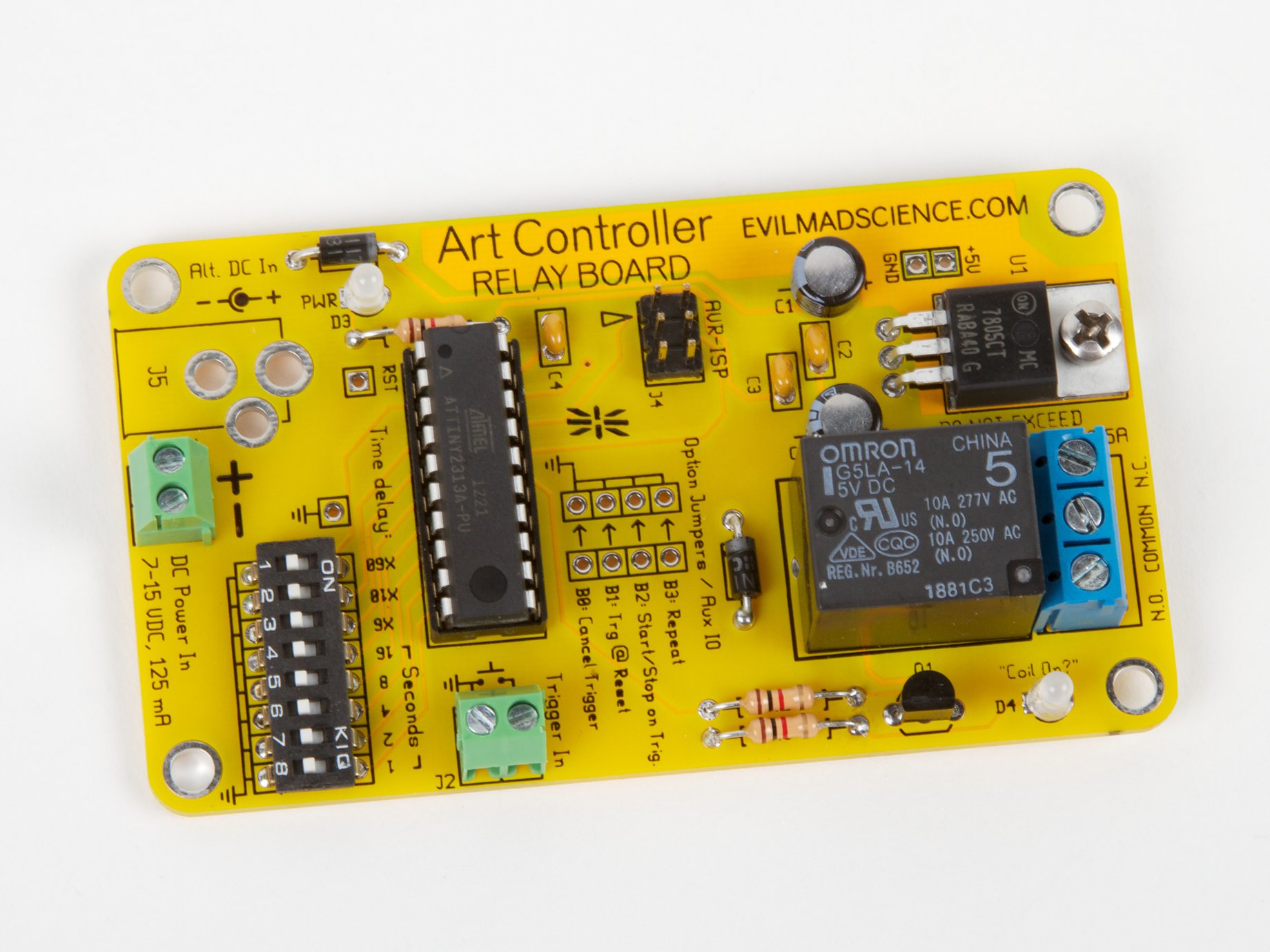
The Art Controller is a multitalented, stand-alone relay module with microcontroller based timing and logic. Easier to adjust and more versatile than most other low-cost time-delay relay modules, the Art Controller can switch AC or DC loads and is reprogrammable to handle the most specialized applications.
The Art Controller gets its name from its inspiration. It was originally suggested by San Francisco Bay Area kinetic artists Christopher T. Palmer and Nemo Gould as a stand-alone device for triggering activating electronic art pieces that need to run for a little while after a button is pressed or a coin is inserted into a slot. And while it can do that (very well), it can be used in countless other jobs where you need to switch on (or off) an electronic load with a relay and timer.
Unless configured otherwise, the behavior of the Art Controller is such that the relay coil energizes as soon as a trigger is received. It stays energized for one delay period (the length of time set by the DIP switches) and then turns off the coil until the next trigger is received.
Triggering: The Art Controller can have its cycle triggered by an external button or switch, or by an external input signal. To use an external button or switch: Connect the two pins of the Art Controller's trigger input to a normally open ("NO") button switch. When the button is pressed or the switch is thrown, it connects the two pins of the trigger input together, triggering the Art Controller. Instead of hooking up a button, you can hook up any external logic-level signal to the trigger input, for example from a light sensor or motion sensor. The Art Controller will perceive a low-going signal the same as it would a button press.
Configuration options and auxiliary inputs: Besides the trigger input and the timing DIP switches, there are four additional I/O pins that can be used as auxiliary I/O pins or as configuration jumpers:
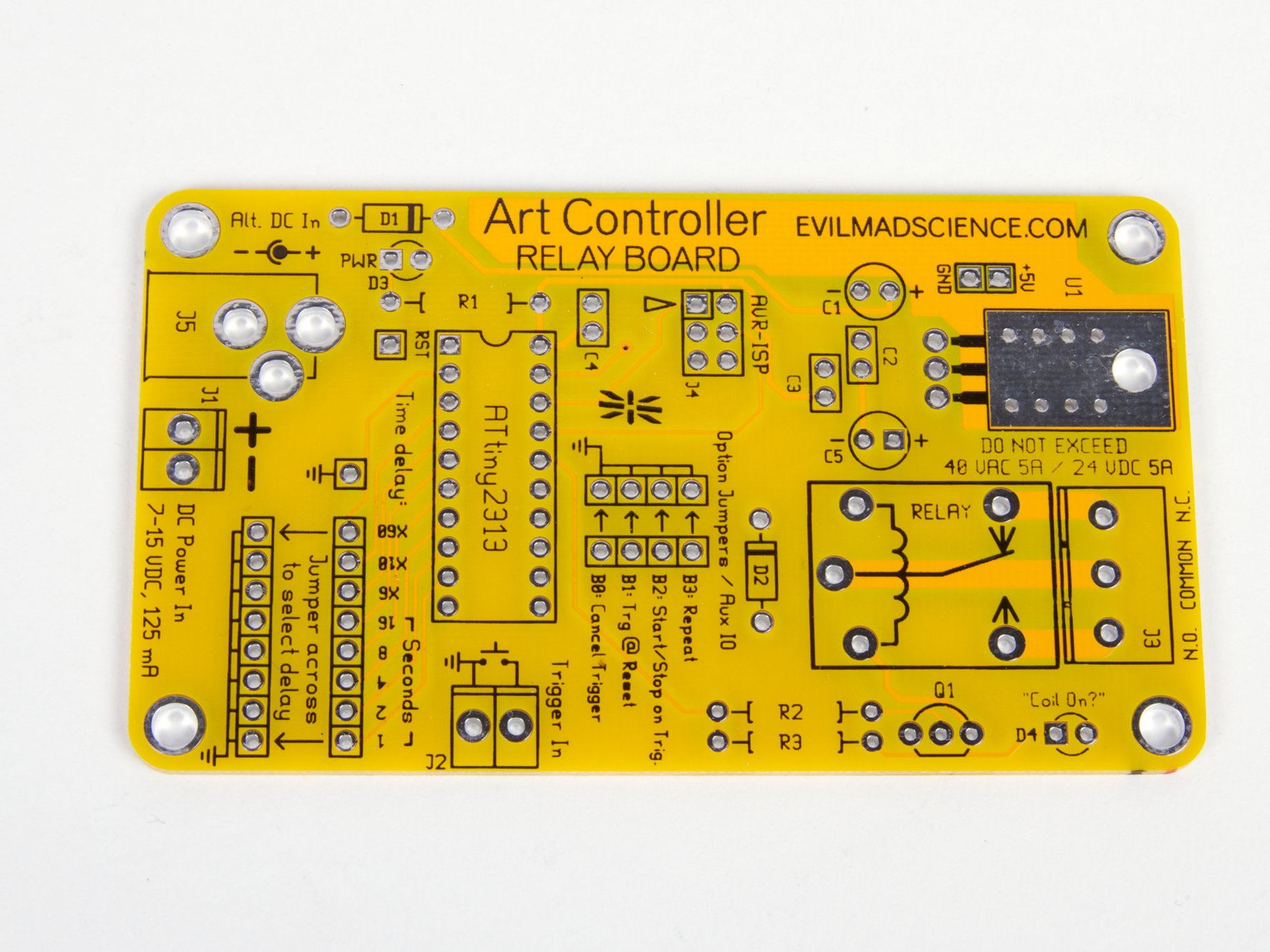
Mechanical relays and configuration: The relay on the Art Controller is an electromechanical type: A mechanical switch that is flipped by an electromagnet when energized. The relay is an "SPDT" type, meaning that it can be used either as a normally-open or normally-closed relay. When idle, the "Common" terminal of the output terminal block is connected to the "NC" terminal, and when the coil is energized, the "Common" terminal is instead connected to the "NO" terminal. When power is removed from the coil (or from the Art Controller as a whole), the relay reverts to its idle state. Thus, depending how you hook it up, it can be used to either turn on or turn off an external load when the coil is energized.
Documentation: The Art Controller is an open source hardware project. The electrical schematic, bill of materials, circuit board design files, and assembly guide are available at the Evil Mad Scientist Wiki.
Standard features
Hardware features:- Recommended load rating: 24 V DC/40 VAC, 5 A (10 A, normally-open, only).
- Screw terminals for relay contacts.
- DIP switches to set timing.
- Power indicator and relay state indicator LEDs.
- On-board 5 V regulator; runs from 7-15 V DC, or can be run from 5 V directly.
- Screw terminals for trigger and input power. Location for optional DC power barrel jack.
- Preprogrammed AVR Microcontroller (Atmel ATtiny2313A), with 6-pin programming header
- Time delay can be set from 1 second to 31 hours.
- Time delay is set by DIP switches; no need to guess and check timing with an adjustment dial.
- Auxiliary cancel-trigger input, halts operation immediately.
- Can be triggered by any low-going signal, or external button, switch, or coin acceptor.
- Can be run as a one-shot or repeating (automatic cycling) timer.
- Can be configured to cancel the trigger if a second trigger input is received.
- Can be set to automatically trigger at power-on.
Usage
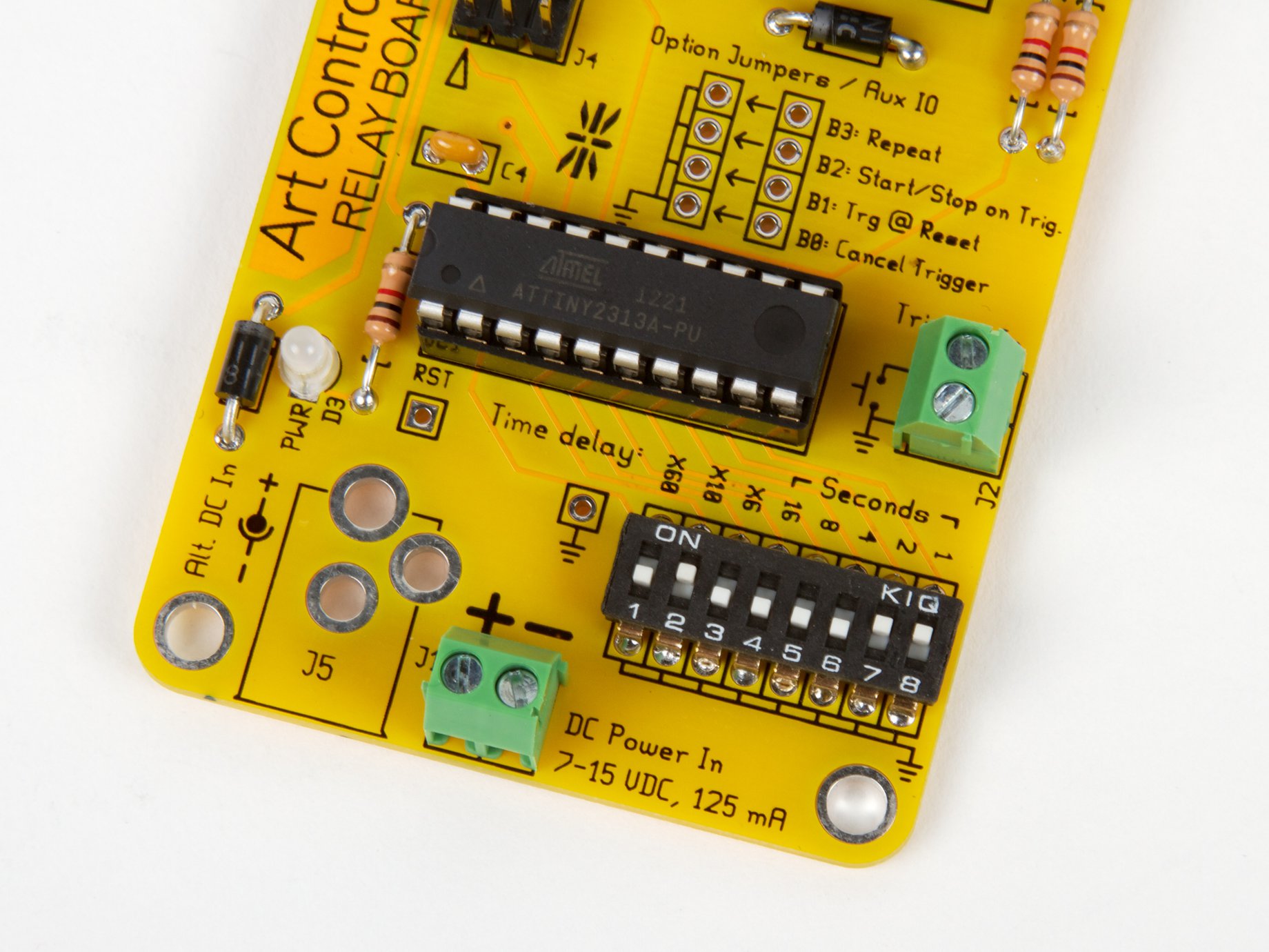
Timing: The relay timing of the Art Controller is performed by the internal clock of the on-board microcontroller, and the delay time is configured with the DIP switches. Using the DIP switches, it is possible to select delay periods ranging from 1 second to 31 hours. The DIP switches have five numeric values (1, 2, 4, 8, and 16 seconds), and three multipliers (×6, ×10, and ×60). The numeric part can be adjusted to add up to any value between 1 s and 31 s, and the multipliers allow these values to be scaled up into the following ranges of nominal delay times:- 1 s — 31 s
- 6 s — 186 s (3 minutes and 6 seconds), in 6 second increments
- 10 s — 310 s (5 minutes and 10 seconds), in 10 second increments
- 1 m — 31 m, in 1 minute increments
- 6 m — 186 m (3 hours and 6 minutes), in 6 minute increments
- 10 m — 310 m (5 hours and 10 minutes), in 10 minute increments
- 1 h — 31 h, in 1 hour increments
Unless configured otherwise, the behavior of the Art Controller is such that the relay coil energizes as soon as a trigger is received. It stays energized for one delay period (the length of time set by the DIP switches) and then turns off the coil until the next trigger is received.
Triggering: The Art Controller can have its cycle triggered by an external button or switch, or by an external input signal. To use an external button or switch: Connect the two pins of the Art Controller's trigger input to a normally open ("NO") button switch. When the button is pressed or the switch is thrown, it connects the two pins of the trigger input together, triggering the Art Controller. Instead of hooking up a button, you can hook up any external logic-level signal to the trigger input, for example from a light sensor or motion sensor. The Art Controller will perceive a low-going signal the same as it would a button press.
Configuration options and auxiliary inputs: Besides the trigger input and the timing DIP switches, there are four additional I/O pins that can be used as auxiliary I/O pins or as configuration jumpers:
- Cancel Trigger. A low-going input on this line can be used to revert the Art Controller to the un-triggered (idle) state. If the input is held low (e.g., connected to ground), it will also prevent any new triggers from being accepted. You can use this to add on an "STOP" button, or you can connect it to a switch to temporarily lock-out the trigger button.
- Trigger @ Reset. You can solder a wire between this pin and ground to configure this option. If configured, the Art Controller will register a trigger (as though you had pressed a trigger button) when it first powers on.
- Start/Stop on Trigger. You can solder a wire between this pin and ground to configure this option. If configured, the Art Controller will treat a second trigger signal as a "cancel" signal. In other words, if you press a trigger button one time, the Art Controller begins its cycle, but if you press it a second time, it will stop the cycle. (If this option is not configured, additional triggers beyond the first will be ignored so long as a cycle is in progress.)
- Repeat. You can solder a wire between this pin and ground to configure this option. Normally, when the Art Controller receives a trigger, it energizes the coil for the specified delay time and then goes back to the idle state. When the repeat option is configured, a trigger instead begins a continuous cycle where the coil is alternately energized and off, each for the specified delay period. The cycle can be halted by using the Cancel input, by pressing the trigger again (if Start/Stop on Trigger is configured), or by removing power from the Art Controller.
Mechanical relays and configuration: The relay on the Art Controller is an electromechanical type: A mechanical switch that is flipped by an electromagnet when energized. The relay is an "SPDT" type, meaning that it can be used either as a normally-open or normally-closed relay. When idle, the "Common" terminal of the output terminal block is connected to the "NC" terminal, and when the coil is energized, the "Common" terminal is instead connected to the "NO" terminal. When power is removed from the coil (or from the Art Controller as a whole), the relay reverts to its idle state. Thus, depending how you hook it up, it can be used to either turn on or turn off an external load when the coil is energized.
Powering the Art Controller
The Art Controller requires DC power to operate the microcontroller and relay. It features an on-board linear voltage regulator and accepts input power in the range of 7-15 V DC. (A 9 V or 12 V DC power supply will work nicely.) Your power supply should have the capacity to supply up to 125 mA. If you prefer, it is also possible to instead configure the Art Controller to operate directly from a regulated 5 V DC power supply by omitting the regulator during assembly. (See documentation for additional details.) The Art Controller has an on-board two-pin screw-terminal block for connecting to power. You can also add an optional barrel jack (sold separately) for connecting to a plug-in power supply. Typical power consumption is approximately 95 mA when the coil is energized and 13 mA when idle.Programming the Art Controller
The Art Controller is an open-source, hackable relay board that can be reprogrammed. While no programming is required— the microcontroller comes preprogrammed to do everything listed above — the Art Controller's onboard ATtiny2313A microcontroller can be reprogrammed in circuit with an AVR ISP programmer, such as the USBtinyISP, to make either minor or radical changes to its behavior. You can vary the timing, the way timing is used, or do anything else that you care to, with up to 16 available digital I/O lines. To give you just a few ideas, here are some things that you could reprogram the Art Controller to do:- Use much shorter or longer delays.
- Wait for a fixed amount of time between being triggered and starting the relay cycle
- Trigger only when the input signal stays high for a certain amount of time.
- Trigger automatically when a certain amount of time passes without otherwise being triggered.
- Trigger only when a set of digital inputs (up to 16 digital inputs) meet a specific set of high and low conditions.
- Control the time delay with the digital inputs.
- Trigger at (pseudo) random intervals.
- Operate as a repeating timer, with different duty cycles.
- Activate for a (pseudo) random amount of time.
- Work as a "pulse" driver, only turning on the relay when the input is high.
- Output a clock or sync signal, even when the module isn't triggered.
- Output a sync signal with the same or opposite sign of the relay state.
- Turn on a warning LED or siren a few moments or minutes before turning on the relay.
Building the Art Controller
The Art Controller is sold as an easy-to-build soldering kit [?]. It includes the circuit board, pre-programmed ATtiny2313A microcontroller, Omron model G5LE-14 relay, 5 V regulator, screw terminal blocks for electrical power and trigger input, relay drive transistor, flyback and isolation Schottky diodes, and an LEDs to indicate power and when the relay coil is energized. To build the Art Controller, basic electronic soldering skill and tools are required, but no additional knowledge of electronics is presumed or required. You provide standard soldering tools: a soldering iron + solder and small ("flush") wire clippers, as well as a small flathead screwdriver for adjusting the screw terminals. The kit features easy "through-hole" construction ("No surface-mount nothin' nowhere!"), and (assuming that you have prior soldering experience) should take roughly half an hour to build. Note that you will need internet access to view the assembly instructions.Documentation: The Art Controller is an open source hardware project. The electrical schematic, bill of materials, circuit board design files, and assembly guide are available at the Evil Mad Scientist Wiki.
Contact ratings and safety
While the relay contacts are rated for AC loads of as high as 120 V (or higher, under some circumstances), we have labeled the Art Controller for loads of up to 40 V AC. Do not exceed this value without providing an external housing that protects fingers and foreign objects from exposure to that voltage. If you choose to exceed our rating (at your own risk), be certain that you have thoroughly addressed the safety issues and taken any additional measures as necessary to ensure that the board can be operated safely. At a minimum, your external enclosure should prevent unintended access to the relay terminals and the underside of the board. The Art Controller is labeled with a current rating of 5 A. However, as per the relay's datasheet, it can be safely operated as high as 10 A (AC or DC) if configured strictly as an N.O. (normally open) relay, with nothing connected to the N.C. terminal. Please refer to the relay's data sheet (PDF) for additional specifications.You may also be interested in...


Home > Products > Soldering Kits